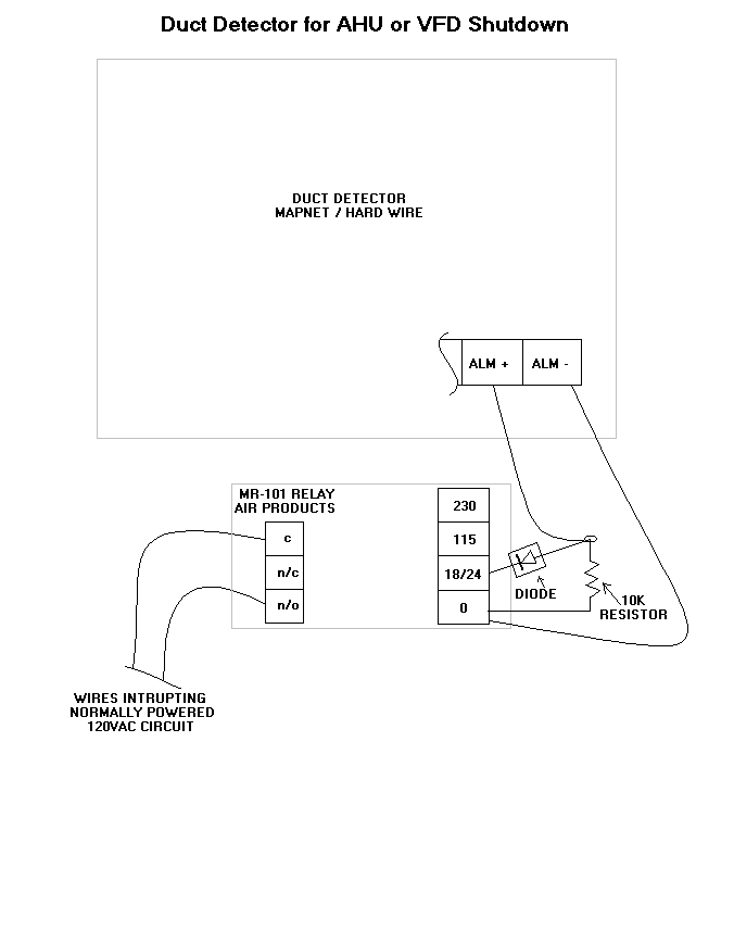
Air Products Duct Detector Wiring Diagram
Firstly the stator winding is connected in star and t. Air flowing through the duct is forced into the air intake (inlet) tube via the air intake holes, (facing the airflow) and passes over the detector head.

Air Flow Sensor Temco Controls Ltd.
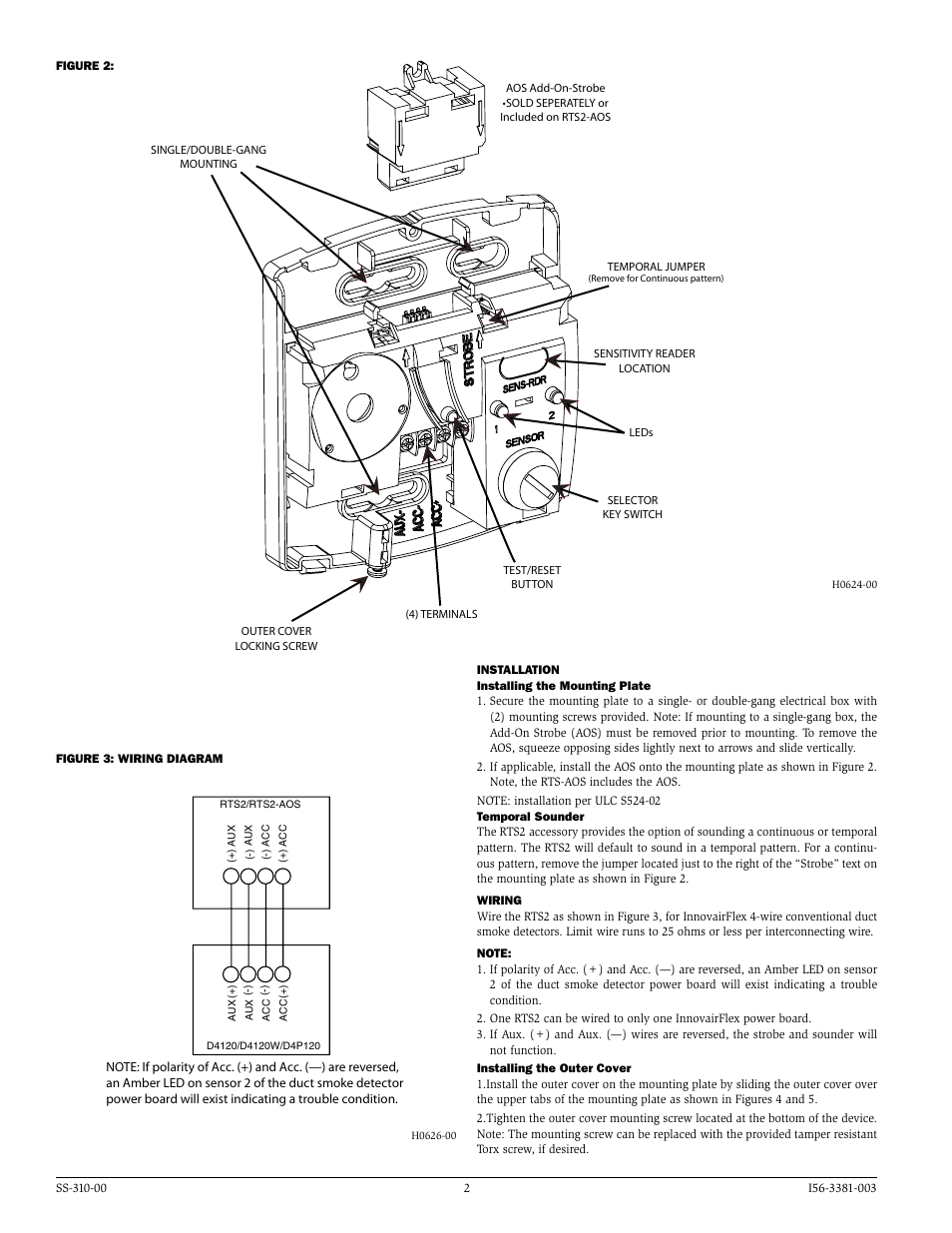
The devices are constructed of attractive yet durable brushed stainless steel and mount on a standard single or double gang electrical box.
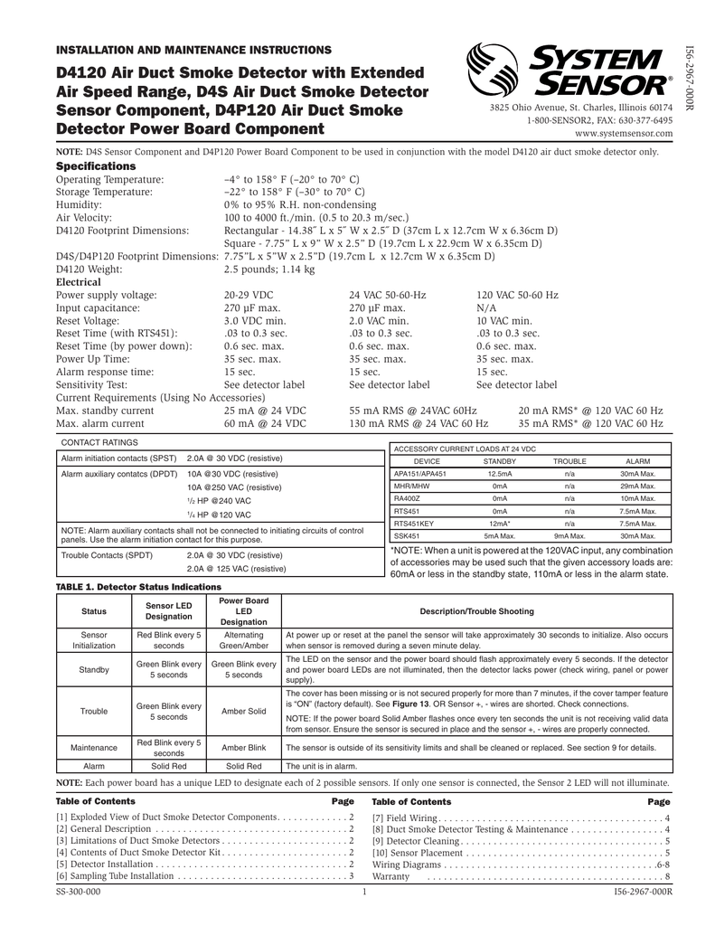
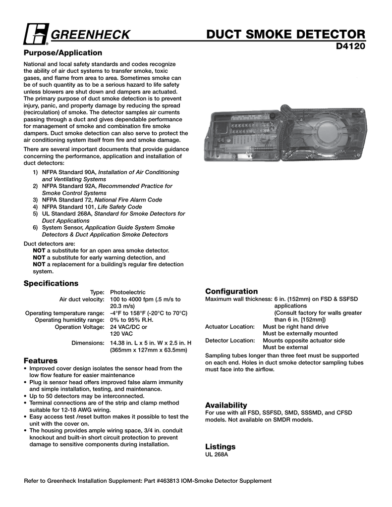
Air products duct detector wiring diagram. Truealarm photoelectric sensors use a stable, pulsed infrared led light source. Air products duct detector wiring diagram tuesday, 18 january 2022 edit. The air duct smoke detector shall be a system sensor innovairflex™ d4120 photoelectric duct smoke detector.
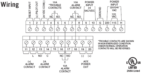
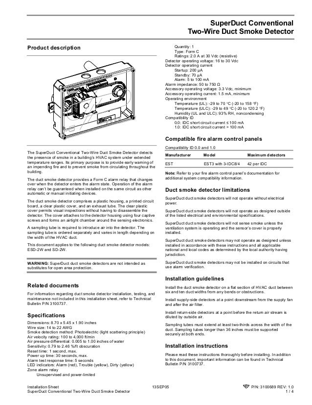
2 sets form “c” rated at 10a @ 115vac resistive. Sampling tubes come installed into the duct allowing air to be direct to the smoke sensor mount in the housing. The flexible housing of the duct smoke detector fits multiple footprints from square to rectangular.
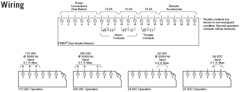
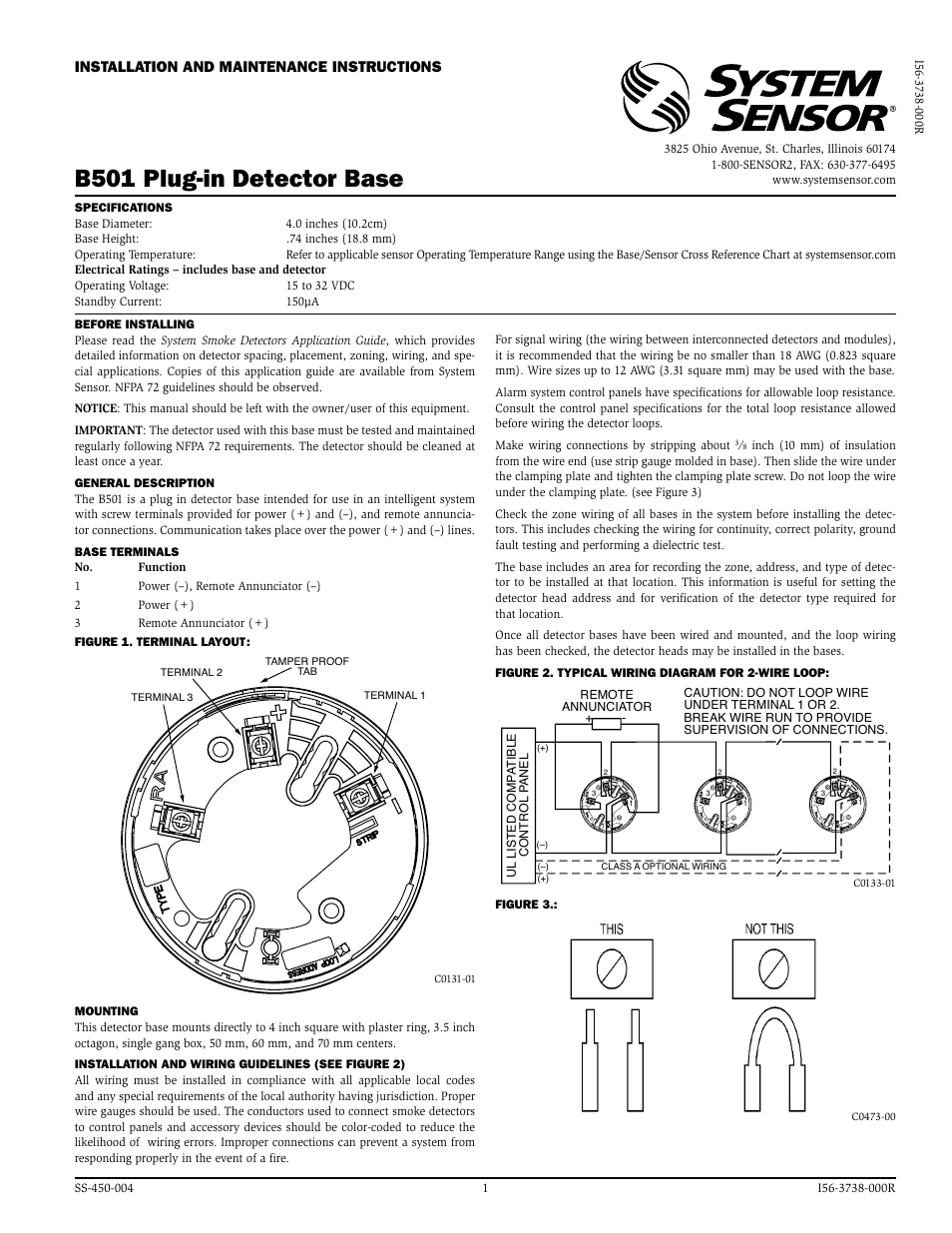
Duct smoke detector range notifier. Following wiring diagrams are applicable only to compatible, current limited, ul listed remote accessories from air products and controls. Use of any other devices may result in damage to the duct smoke detector, potential injury, and will void any applicable warranties.
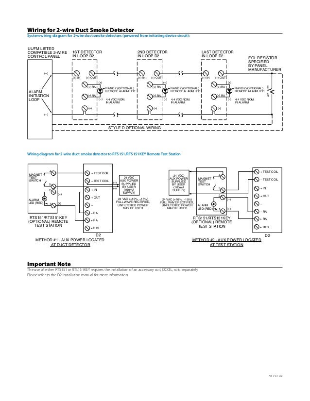
The air will be drawn out via the exhaust tube back into the hvac duct. Air products duct detector wiring diagram. Wiring diagrams.4,6 warranty.6 the d2 model is a photoelectric detector approved for an extended air speed.
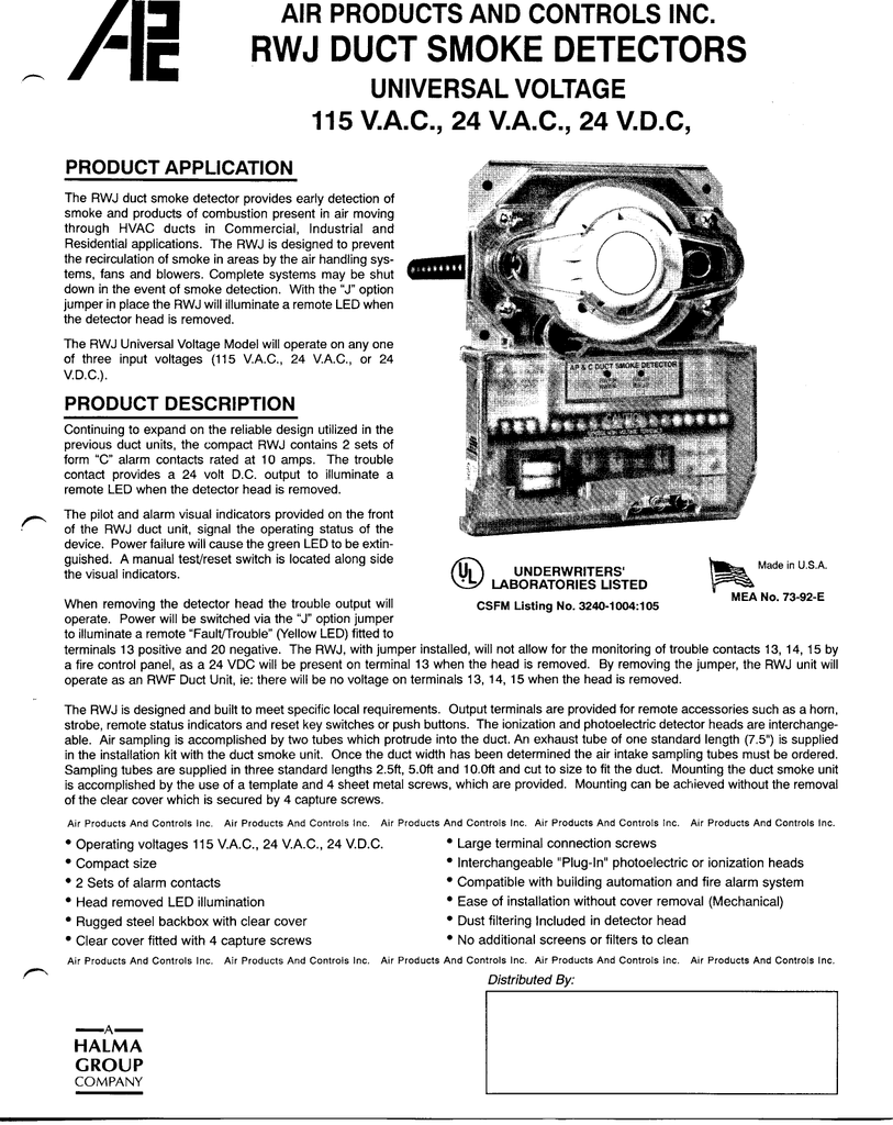
The latest innovation for early detection of smoke and products of combustion present in air moving through hvac ducts in commercial and industrial applicati. For example the hole for air conditioner wiring should be 2 feet directly above the units condensation lines. Each component should be placed and connected with other parts in specific way.
Two tubes extend into the hvac duct. The unit is designed to prevent the recirculation or spread of smoke by air. 4 wire air duct smoke detector protection systems.
Air products and controls inc. Air products duct detector wiring diagram. Use of any other devices may result in damage to the duct smoke detector, potential injury, and will void any applicable warranties.
Re alarm led red blac k strobe and/or horn green pilot led k red black yellow trou ble led jumper re d black yellow trouble le d. When smoke is detected in a duct, the unit communicates the condition to the intelliknight control panel. Smoke detectors designed for use in air duct systems are used to sense the presence of smoke in the duct.
The detector housing shall be ul listed per ul 268a specifically for use in air handling systems. Air products controls product application the sl‑2000 series conventional duct detector is the latest innovation for early detection of smoke and products of combustion present in air moving through hvac ducts in commercial, industrial, and residential applications. This detector was developed to constantly monitor the air within a duct and to detect the presence of smoke.
Factory wiring diagrams dsdn factory wired to fsd with efl use terminals 1 2 for 120vac power supply shown. An alarm is activated when the quantity (percent obscuration) of combustion products in that air sample exceeds the detector’s sensitivity setting. For example the hole for air conditioner wiring should be 2 feet directly above the units condensation lines.
The operating principle of a duct detector is based on the venturi effect. Air velocity in the duct as low as 100 ft/min. It shows how a electrical wires are interconnected and will also show where fixtures and components could be attached to the.
The ms series remote accessories are designed to be used with air products & controls duct smoke detectors to provide audible and visual indication as well as remote test/reset functions. Following wiring diagrams are applicable only to compatible, current limited, ul listed remote accessories from air products and controls. Air compressor wiring diagram 230v 1 phase.
Sm 501 series duct smoke detectors 4 wire ionization type photoelectric type. Superduct detectors continually sample air flow in the hvac duct and initiate an alarm condition whenever smoke is detected. Quiescent current alarm current 24vac 50ma 24vac.
1 form “a” rated at 2a

Toyota Tundra Ambient Air Temperature Sensor. COOLER (AMBIENT TEMP. SENSOR); THERMISTOR
Duct Detector Wiring Diagram how small can words be tattooed news
System Sensor D4120 Wiring Diagram

Toyota Yaris iA Ambient Air Temperature Sensor. CONTROL, PANEL, DUCT 88790WB001 Genuine
Firex 2650760 Ionization 115/230 VAC Universal Voltage Duct Smoke Detectors

Toyota Sienna Cabin Air Temperature Sensor. STONE 8862545020B0 Koch 33 Toyota, Easton PA

System Sensor D4120 Wiring Diagram

Lexus RX 350L Duct, heater to register, no. 1. Air, sensor, control 558430E090 Prestige

Lexus RX 400h Duct subassembly, air, no. 1. Control, sensor, panel 872010E010 Rallye Lexus

System Sensor D4120 Wiring Diagram Dh1851ac Datasheet Pdf Systemsensor Advanced Ideas The
Firex 2650660 Ionization 115/230 VAC Universal Voltage Duct Smoke Detectors

System Sensor D4120 Wiring Diagram
System Sensor D4120 Wiring Diagram
System Sensor D4120 Wiring Diagram Dh1851ac Datasheet Pdf Systemsensor Advanced Ideas The

System Sensor D4120 Wiring Diagram
Hvac Duct Wiring A Smoke Detector In Hvac Duct
System Sensor D4120 Wiring Diagram / System Sensor D4120 to RTS. Wiring and testing procedure
The University of Arizona FM Fire Safety
Duct Detector Wiring Diagram how small can words be tattooed news